
The Use of a Force Table
Important!
This worksheet explains the procedures for using a force table correctly.
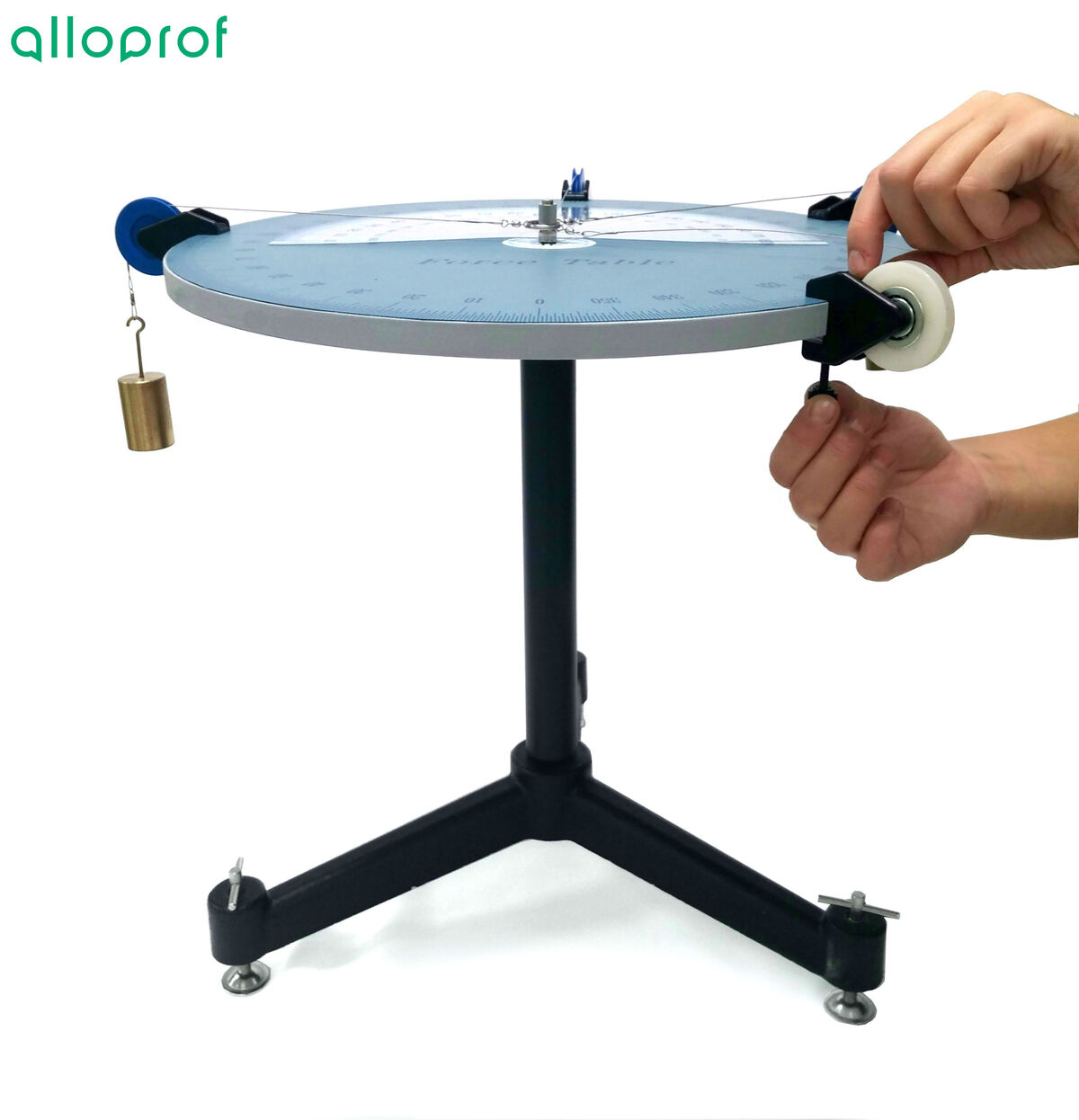
The force table can be used to understand the effect of one or more forces on an object. It can also be used to determine the equilibrant force of a forces system.
Equipment
- Force table
- Level
- Rings
- Strings
- Pulleys
- Set of masses

Procedure
1. Place the force table on the work surface. Using a level, check that the force table is horizontally leveled.

Important!
On most force tables, it is possible to adjust the table's feet to obtain a perfect level. If this step is not correctly completed, the further results could be incorrects, because the masses added in the following steps will adjust the table level.
2. Place the central screw on the force table, and insert the ring with its cords into the central ring.


Be careful!
If the mass to be added to the mass holder is not known and only the force is given, the mass must be determined by isolating it in the gravitational force formula. The mass to be placed in the support is obtained by the following formula:
||m = \displaystyle \frac {F_{g}}{g}||
where
|m| represents the mass to be added |(\text {kg})|
|F_{g}| represents the gravitational force |(\text {N})|
|g| represents the intensity of the gravitational field |(\text {9,8 N/kg})|
6. Repeat steps 3 to 5 for other forces.


7. Pull on the last cord, travelling it around the force table until the ring is perfectly centered in relation to the central rod.

8. Attach a pulley at the angle found in the previous step.
9. Place a cord in this pulley.

10. Hang masses on the cord until the ring is perfectly centered in relation to the central rod and stationary.

11. Calculate the mass added in the last mass holder to calculate the equilibrant force.
12. Put away equipment.
Results
The equilibrant force can be determined using the gravitational force formula.
If masses totalling |\small \text {170 g}| have been added to the mass support to allow the ring to be perfectly centred, what is the equilibrant force of this system?
||\begin{align}m &= 170 \: \text {g} = 0.170\:\text{kg} &g &= 9.8 \: \text{N/kg}\\
F_{g} &= x\end{align}||
||\begin{align} F_{g} =m \times g \quad \Rightarrow \quad F_{g} &=
0.170\: \text{kg}\times 9.8 \: \text {N/kg}\\
&= 1.67 \: \text{N} \end{align}||
Since the angle of the equilibrating force is determined by the position of the pulley, it is therefore possible to determine that the equilibrating force of this system of forces is |\text {1.67 N}| at |\text {308}^{\circ}|.
Be careful!
In the images, the |0^{\circ}| does not correspond to the positive x-axis; we therefore need to start from the point where the positive x-axis is located when we look at the photos and calculate the angles in relation to this reference point.
The experimental result can be compared with the theoretical result expected before the experiment. Below, it explains the mathematical procedure for determining the equilibrant force that should have been obtained.
What was the theoretical resultant force expected from the forces system used in the experiment?
|\overrightarrow {F_1} = \text {0.98 N à 30}^{\circ}|
|\overrightarrow {F_2} = \text {0.49 N à 85}^{\circ}|
|\overrightarrow {F_3} = \text {1.96 N à 170}^{\circ}|
First, the vectors must be decomposed into their components.
| | Horizontal Component | Vertical Component |
| |\overrightarrow { F_1}| | |0.98 \cos 30^{\circ} = 0.85 \:\text {N}| | |0.98 \sin 30^{\circ} = 0.49 \: \text {N}| |
| |\overrightarrow {F_2}| | |0.49 \cos 85^{\circ} = 0.04 \: \text {N}| | |0.49\sin 85^{\circ} = 0.49 \: \text {N}| |
| |\overrightarrow {F_3}| | |1.96 \cos 170^{\circ} = -1.93 \: \text {N}| | |1.96 \sin 170^{\circ} = 0.340 \: \text {N}| |
Once the three vectors have been decomposed, add the horizontal components of each vector together, and do the same with the vertical components.
| | Horizontal Component | Vertical Component |
| |\overrightarrow {F_1}| | |0.85 \: \text {N}| | |0.49 \: \text {N}| |
| |\overrightarrow {F_2}| | |0.04 \: \text {N}| | |0.49 \: \text {N}| |
| |\overrightarrow {F_3}| | |-1.93 \: \text {N}| | |0.340 \: \text {N}| |
| |\text {Sum}| | |0.85 + 0.04 + -1.93 = - 1.04 \: \text {N}| | |0.49 + 0.49 + 0.340 = 1.32 \: \text {N}| |
Once both components have been determined, it's possible to calculate the magnitude of the resulting vector.
||\begin{align} r = \sqrt{x^2 + y^2} \quad \Rightarrow \quad r &= \sqrt{ {(-1.04)^2} + {(1.32)^2}} \\ &= \sqrt{2.91}\\ & \approx 1.68\: \text{N} \end{align}||
To find the angle, we use trigonometric ratios, like the tangent.
||\begin{align} \theta=\tan^{-1} \left( \displaystyle \frac{ {y}}{ {x}} \right)\quad \Rightarrow \quad \theta &=\tan^{-1} = \displaystyle \left( \frac{ {1.32}}{{1.04}} \right)\\
&= \tan^{-1}\left(1.\overline {2}\right)\\
& \approx 51.8^{\circ}\end{align}||
To find out what this angle represents, it's important to represent the vector in a reference system. Since the horizontal component is negative, but the vertical component is positive, the vector will be located in the second quadrant. To obtain the angle of the resultant force, we need to take the difference between |180^{\circ}| and the calculated angle.
||\Theta = 180^{\circ} - 51.8^{\circ} = 128.2^{\circ} \approx 128^{\circ}||
The resultant force therefore has a magnitude of |1.68 \: \text {N}| and an orientation of |128^{\circ}|.
The equilibrant force is of the same magnitude as the resultant force, but in the opposite direction. The magnitude is therefore already known, but the angle needs to be determined. We therefore need to add |180^{\circ}| to the angle of the resultant force.
||\Theta = 128^{\circ} + 180^{\circ} = 308^{\circ}||
The equilibrant force has a magnitude of |1.68 \: \text {N}| and an orientation of |308^{\circ}|. These data or values can be compared with those experimentally obtained.